< Back | Github repository | Project page on Hackaday.io
There's something in the movies I always thought it was pretty cool: that part when someone needs to activate a special device/weapon/whatever by turning a couple of keys at the same time and then pressing a bunch of buttons or using a keypad with an authorization code. The idea of a precise and complex combination in order to perform that powerful and relevant action got me 'cause, well, knobs, buttons, switches and leds blinking.
(btw, this procedures are, more or less, real. Check out the Two-man rule related to the nuclear stuff from the USA and things like that).
And, since the nuclear weapons part is not cool (or, in general, anything involving weapons), what if I build a digital clock that emulates this kind of system in order to turn off the alarm sound once it starts beeping?
|

|
|

|

|
|
|
|
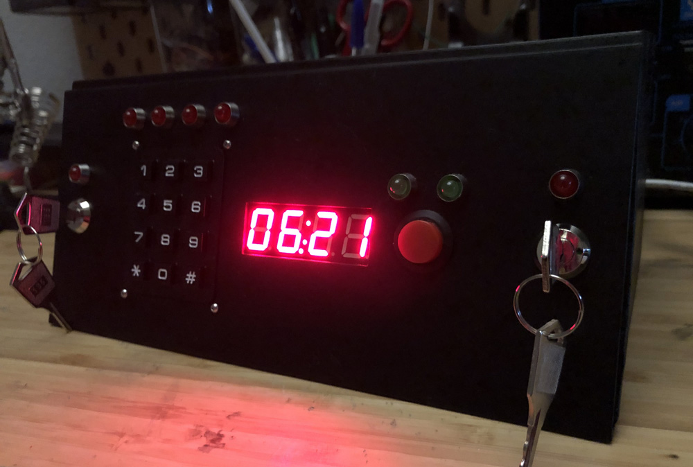
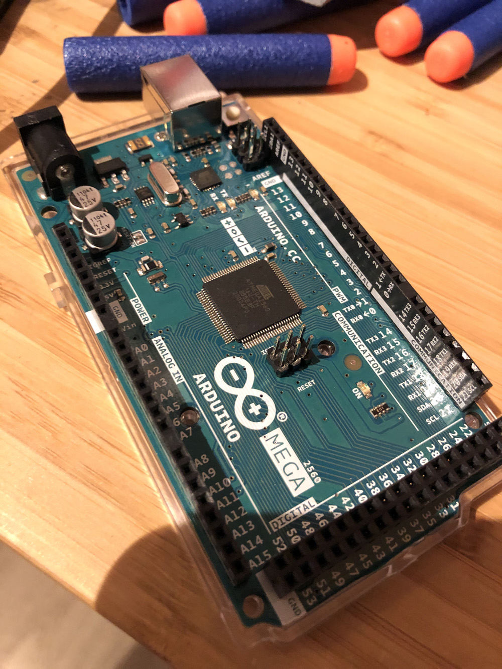
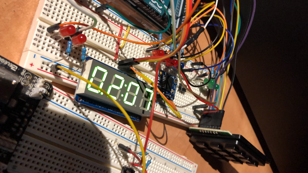
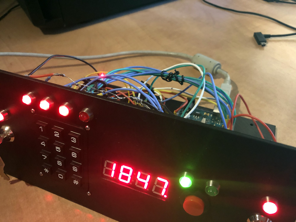
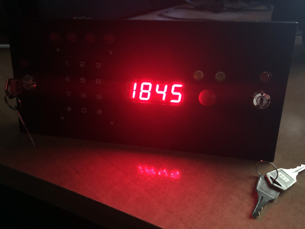
An Arduino-based clock (with an RTC module) that displays the time, triggers an alarm and, most important, handles the unnecessary complex way to turn it off once it's active. See the device beeping and doing alarm clock stuff here!
Some of its features include:
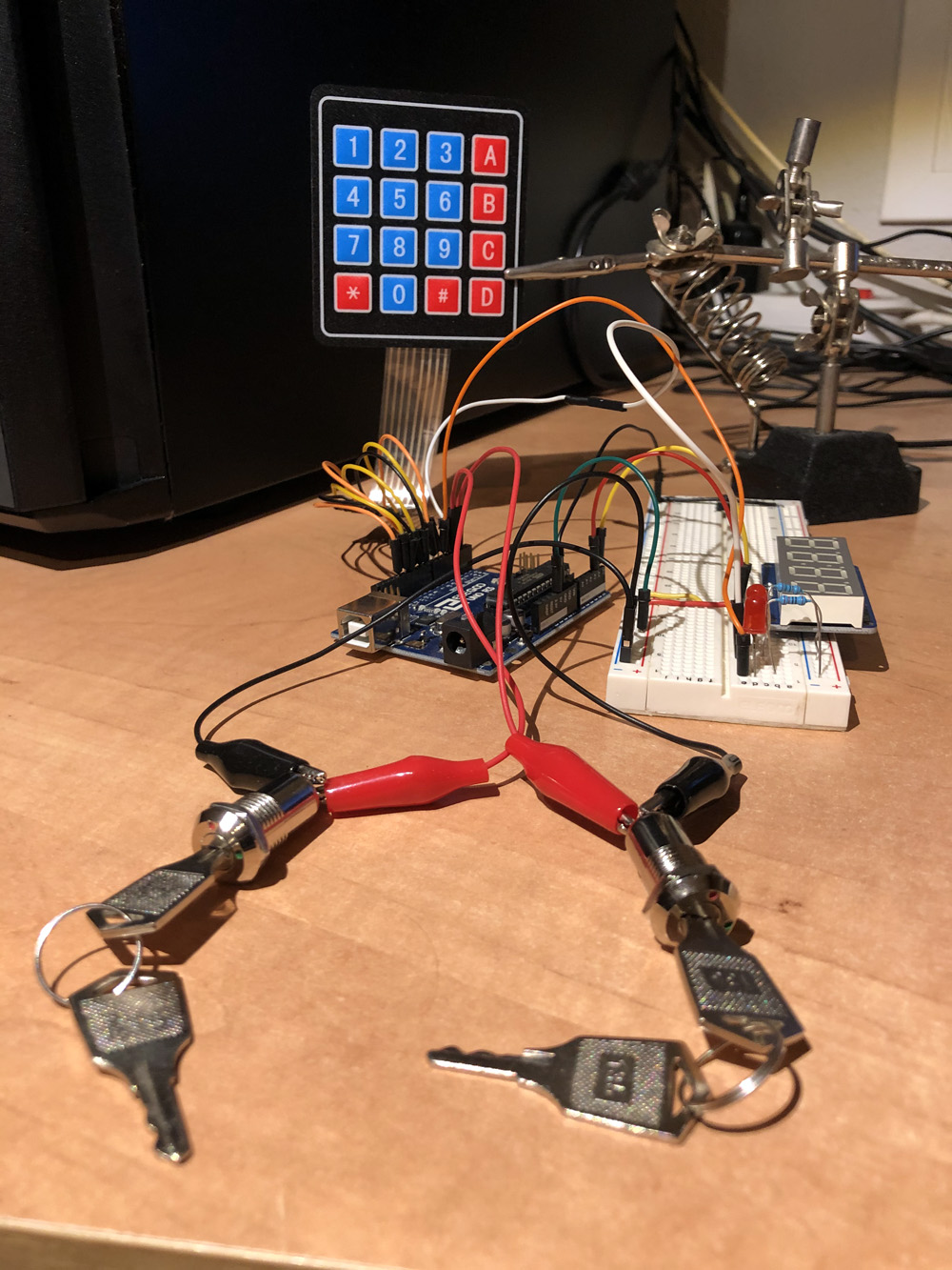
Despite the fact that I've always wanted to build something around that "two-key concept", the idea of putting it inside an alarm clock came to me recently. Based on that, I thought about how many "steps" would be necessary to deactivate the system (in this case, two: the two keys and a numeric code using a keypad).
|
|
|
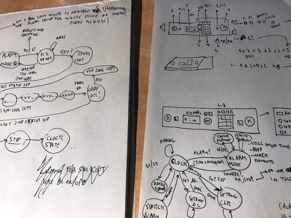
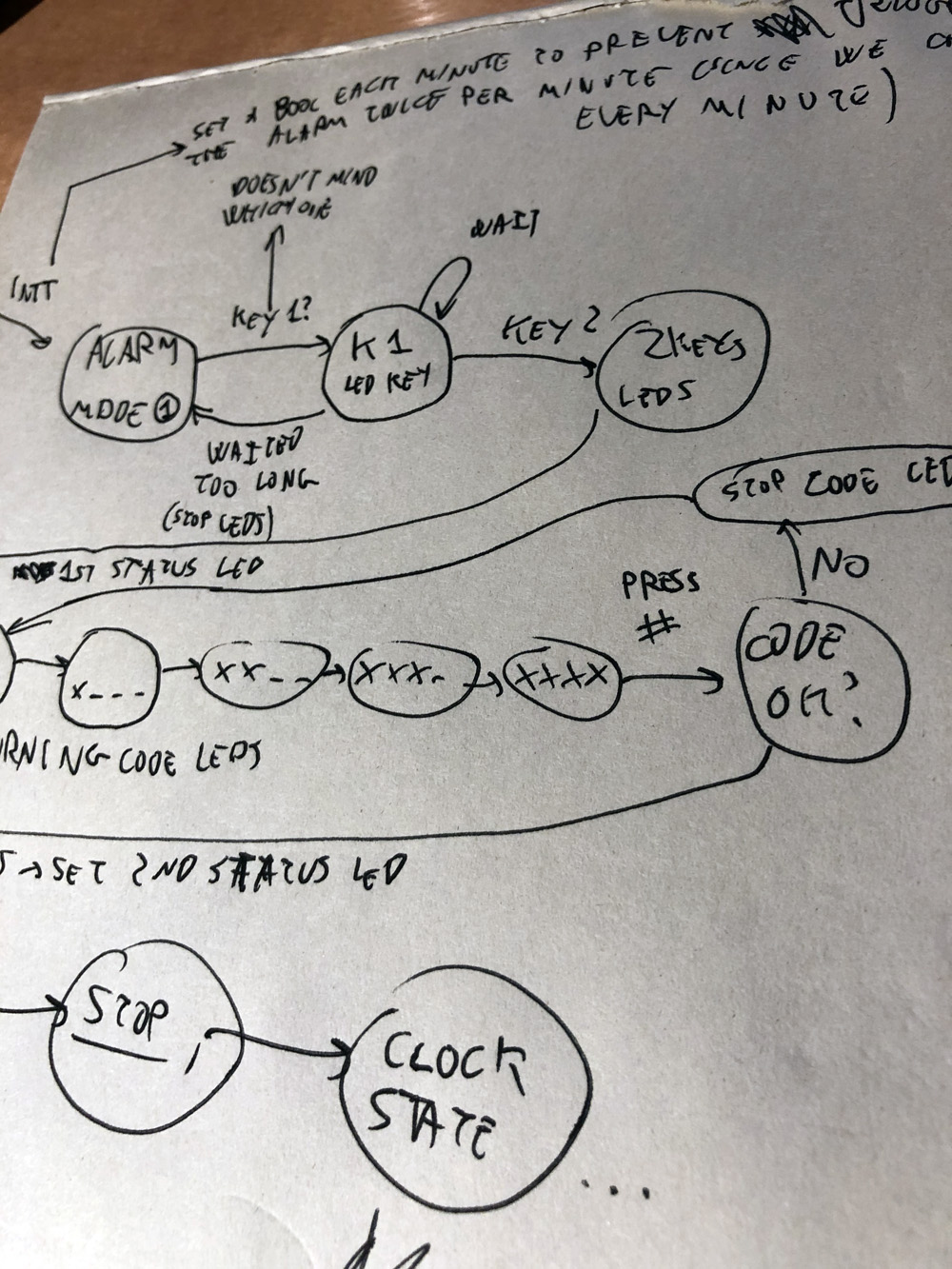
(in my head these drawings made more sense that it might seem, I promise!)
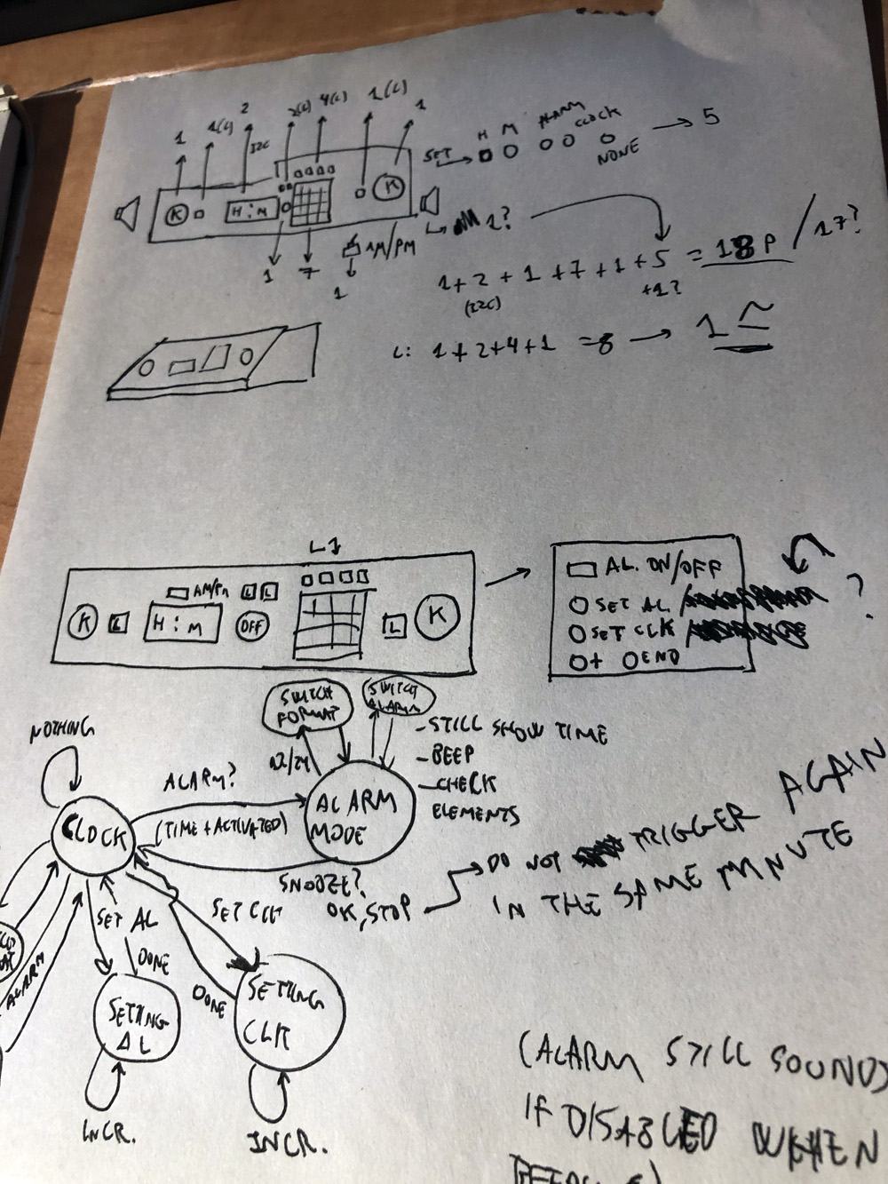
The clock is a simple state machine that works between the clock mode, the alarm mode and the setting mode. When acting as a regular clock (in clock mode) it will show the current time and wait for the alarm trigger. The alarm mode is a step that activates a more complex state machine (an alarm state machine) that will retain the clock state there (beeping the alarm) until all the steps for this other machine are succesfully fullfiled (so the alarm state machine controls all the inputs, the two keys turn action, the keypad code, etc.).
There's also a setting mode the user can enter from the clock mode in order to set the current time and the alarm time.
The alarm mode starts in an "idle" first step which means "do nothing since the alarm has not been triggered yet". After that, the only possible change needs to be done by the alarm triggering itself, advancing to a state in which the alarm is actually beeping and no shutdown sequence has been initiated (no keys turned, no code set, etc.).
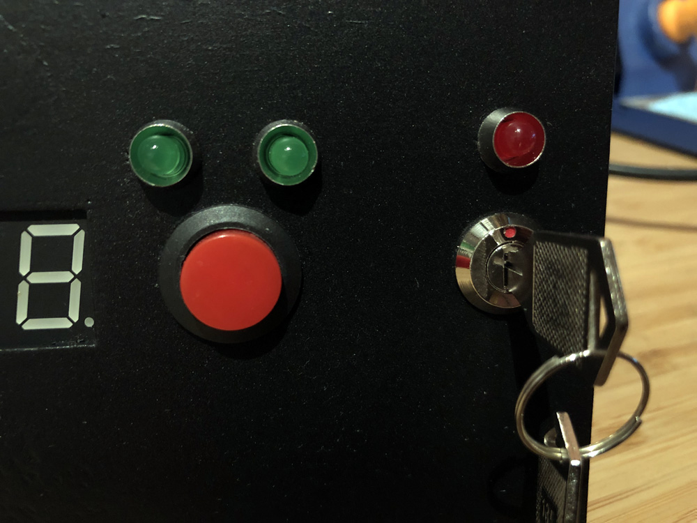
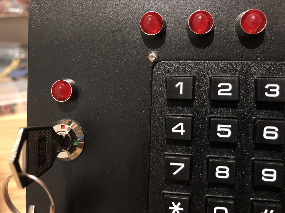
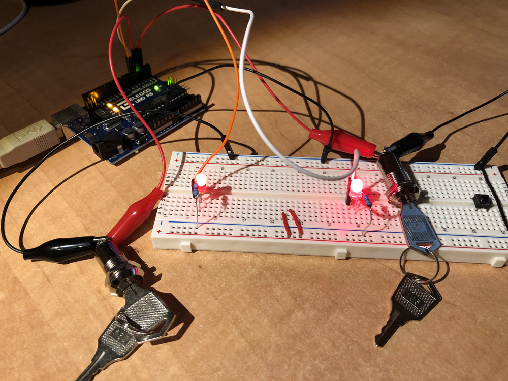
First, both of the keys need to be turned right at the same time. When this action is performed in a proper way (there's a certain delay between one key is activated and the other one is turned too, so there's a "human valid range" in order to avoid checking both of the keys in the same Arduino's clock tick - which I think is something pretty impossible for a human being to do :_D) a code will be required. Once that code is entered correctly (it can be repeated until it's a valid one) a final red button must be pressed to turn off the alarm and go to the initial idle state.
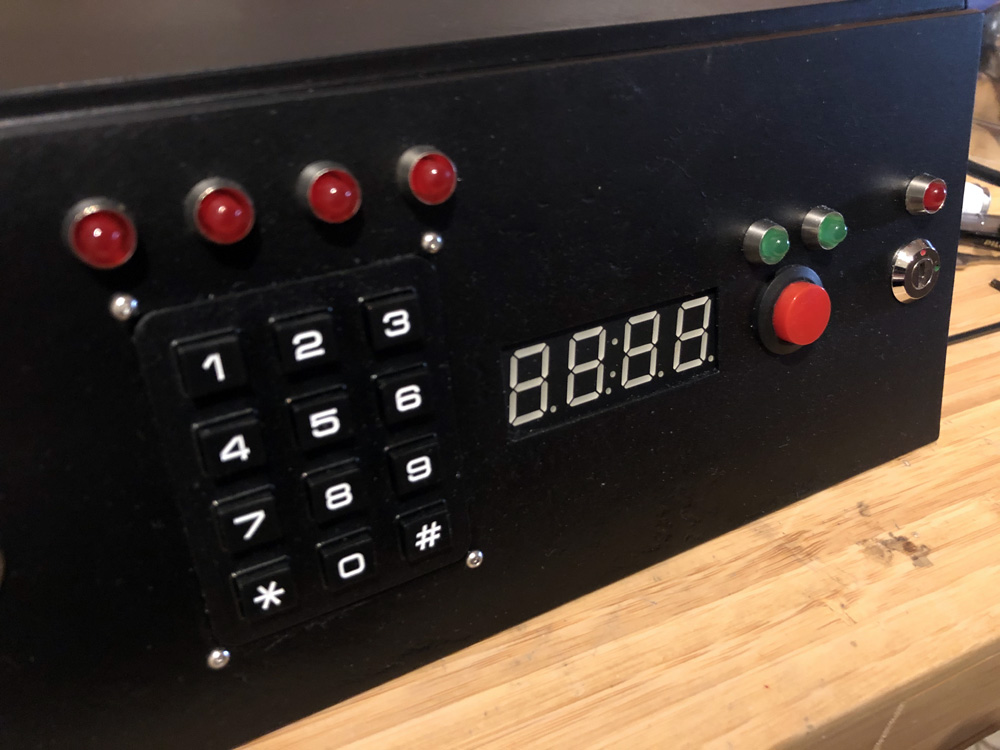
Trying to push the red button before any of the other actions (there're some leds showing every step, so no confusion here) will trigger a reset action that will move us to the full armed status. This will require to re-activate the keys again (basically turn left and right again) and then move to the keypad code.
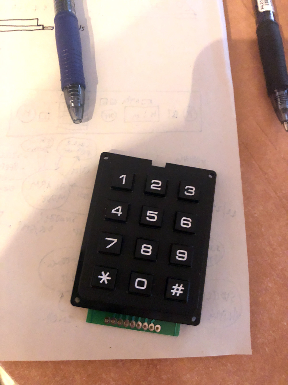
Each of the "physical modules" that we need to complete before the red button is pressed is also a little state machine that works as a closed blackbox: it'll only deliver a "completed", "non-completed" or "idle" status, so the system only needs to ask to each module about their state (leaving the internal settings and checks to that module). Translating this into code means the two keys switches are a full C++ class that is used as "the two_keys object"; and the keypad is known as "the keypad class".
There's a "base" idle state in which nothing can be performed until the alarm is triggered and the two keys system becomes ready. Being ready means "waiting for BOTH of the keys" so each time a discrepancy appears (like changing from "idle" to "no keys activated" having one key already turned, which is something we don't want) we jump to the reset state.
The reset state will wait for a few milliseconds and then try to check if both of the keys are turned off. Otherwise, it'll perform in that state until the desired initial state can be fullfiled (otherwise we could bypass the sequence by just having both of the keys constantly turned on!).
Once a key is activated it'll wait until the second one (that's our best case scenario) and then move to the final state: both keys are currently activated, so the alarm can pick up that state and do other things.
BUT if there's too much time between one key and the other, or if the first one is de-activated before the second one, then we go back to the reset state.
Also notice that once the final state is reached, the keys can be freely turned on and off and nothing will happen (the state has been reached, so this doesn't matter anymore until the alarm resets the whole system).
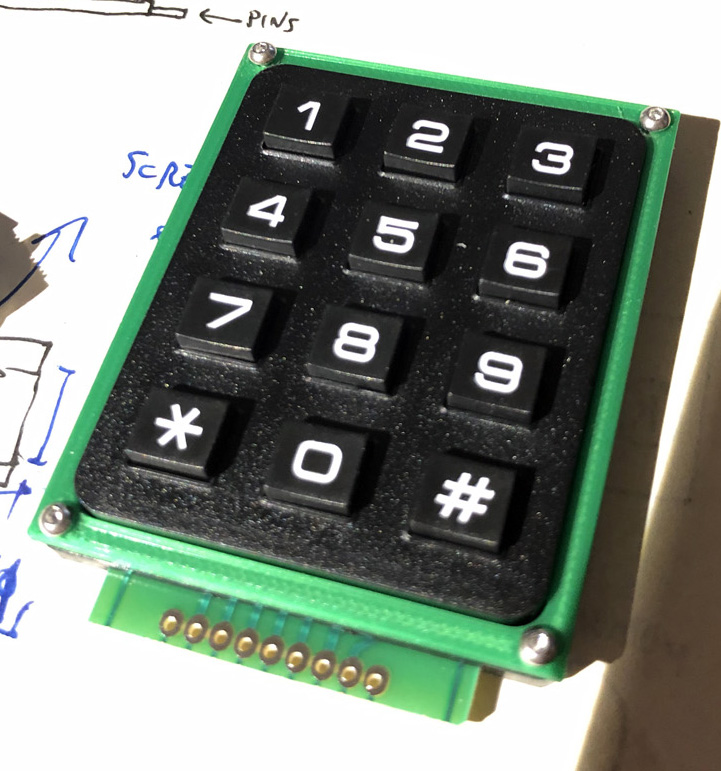
Pretty similar to the two keys module (being idle on the clock, changing to waiting code with the alarm, remaining on the finished state at the end) but with a small difference: while being in idle mode the module can read some keystrokes in order to change to config mode or perform some minor actions like switching between AM/PM - 24h or enabling/disabling the alarm.
It's the main system (or main state machine, main class, whatever you wanna call it...) the one that handles the configuration of the clock, using the keypad module ONLY to fetch the pressed keys but without performing any action by itself.

|
|
|
|
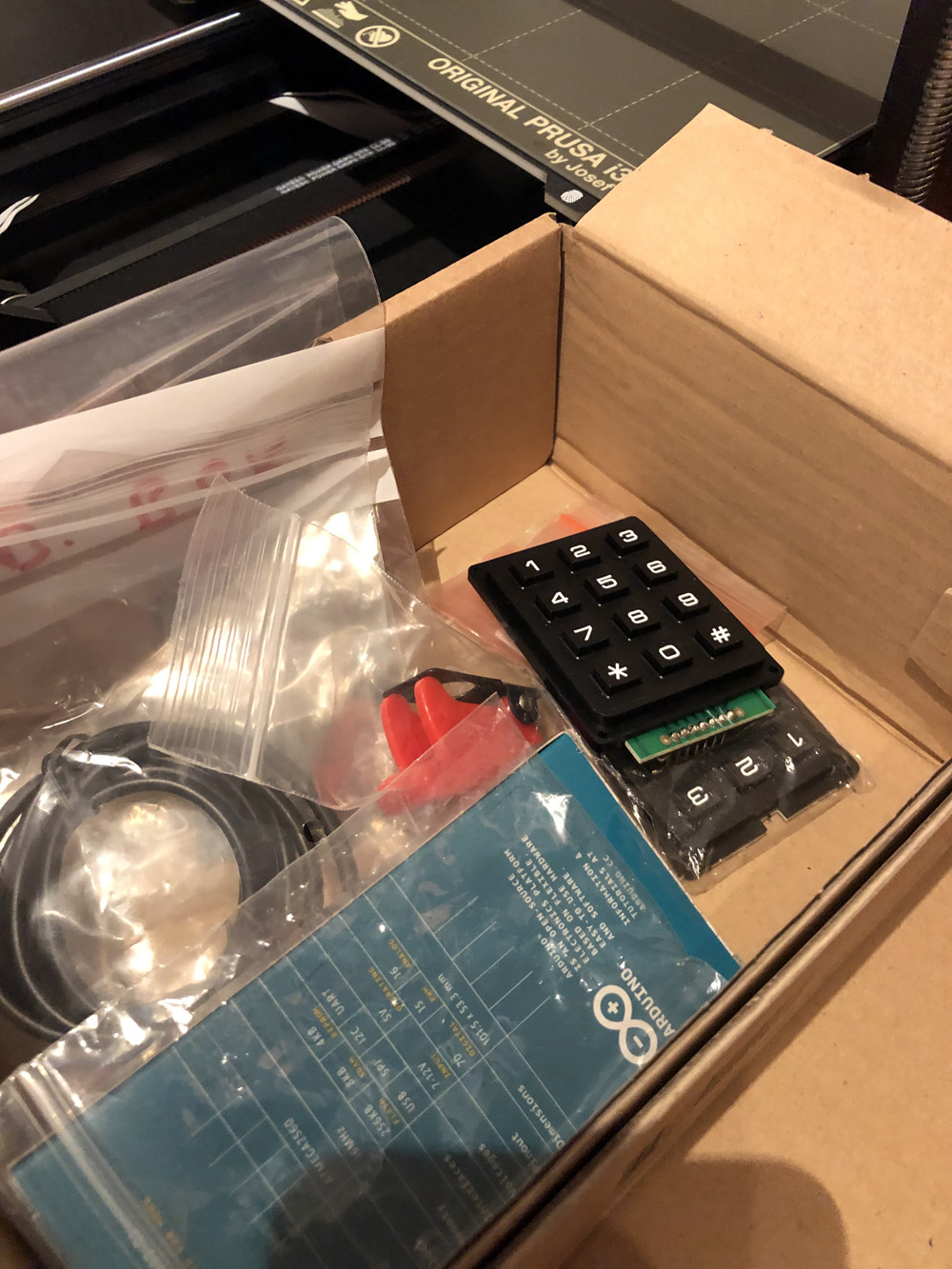
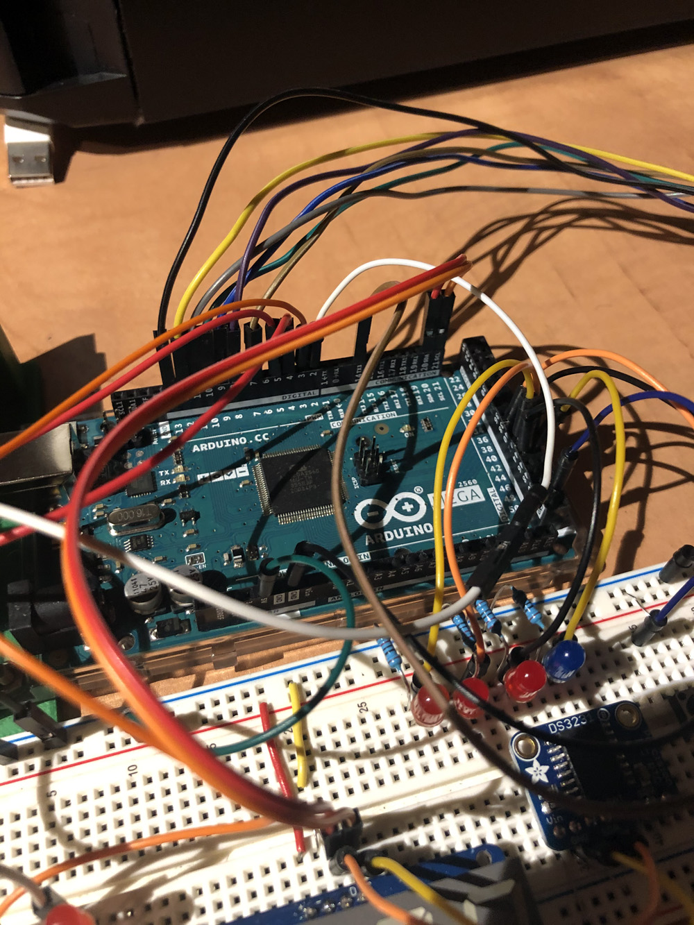
part list:
Once the alarm is triggered a certain pin on the Arduino will go high so we can attach there whatever we wanna show/display/power/beep. In my case I use a 555 timer in an astable mode to create some intervals for the buzzer (powered using a transistor). Needless to say, this signal can be used to trigger any other thing (maybe a relay connected to a more powerful horn?) or even modify it so we doesn't need the astable circuit to buzz using those intervals.
|
|
|
|

|

|
The full code is available on my github page. There we have an Arduino sketch that controls the whole clock logic with the help of some additional classes:
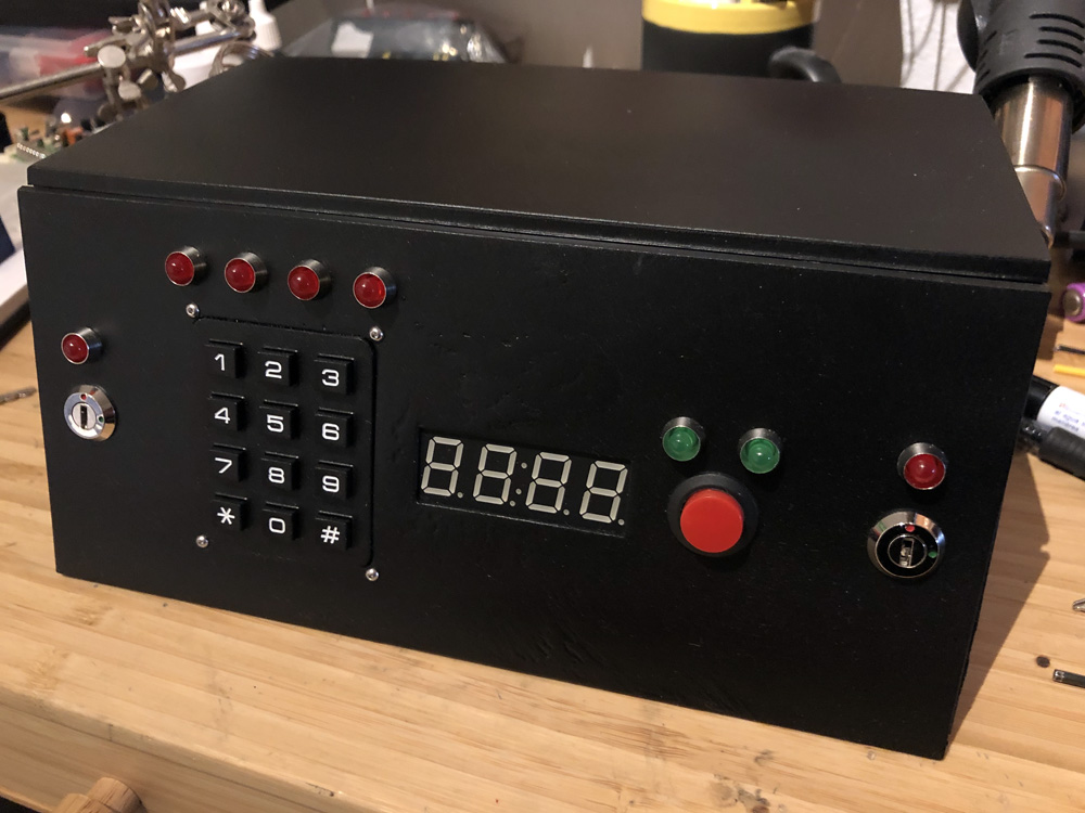
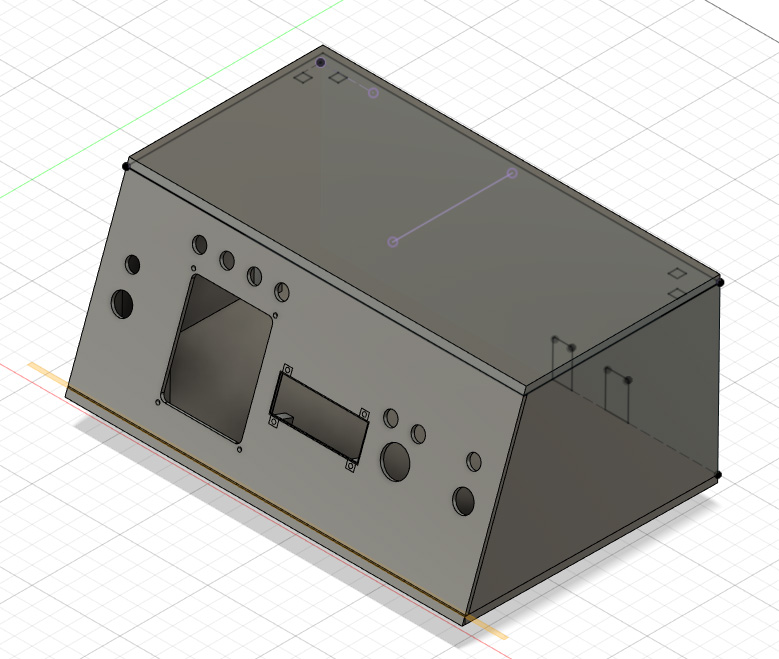
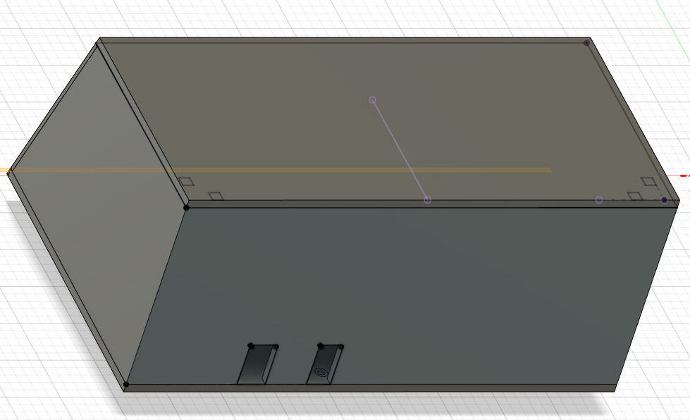
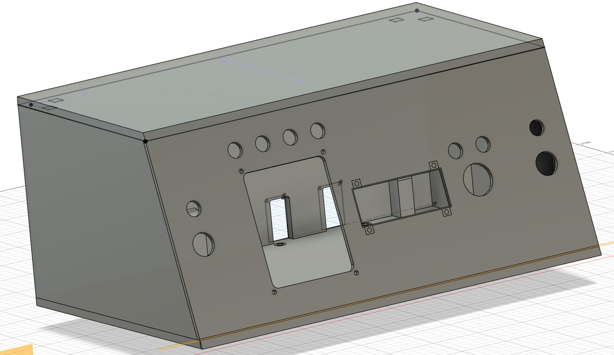
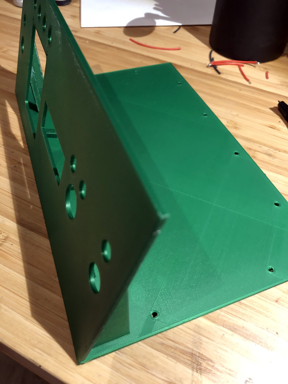
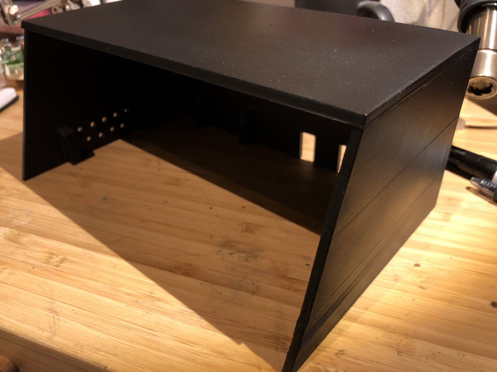
Once everything was working properly, it was time to build a nice box for the clock. I designed it using Fusion 360 and it was one of my first "big projects". Then I 3D-printed it, glued some parts, sanded, painted and put it all together.
|
|
|
|
|
|
|
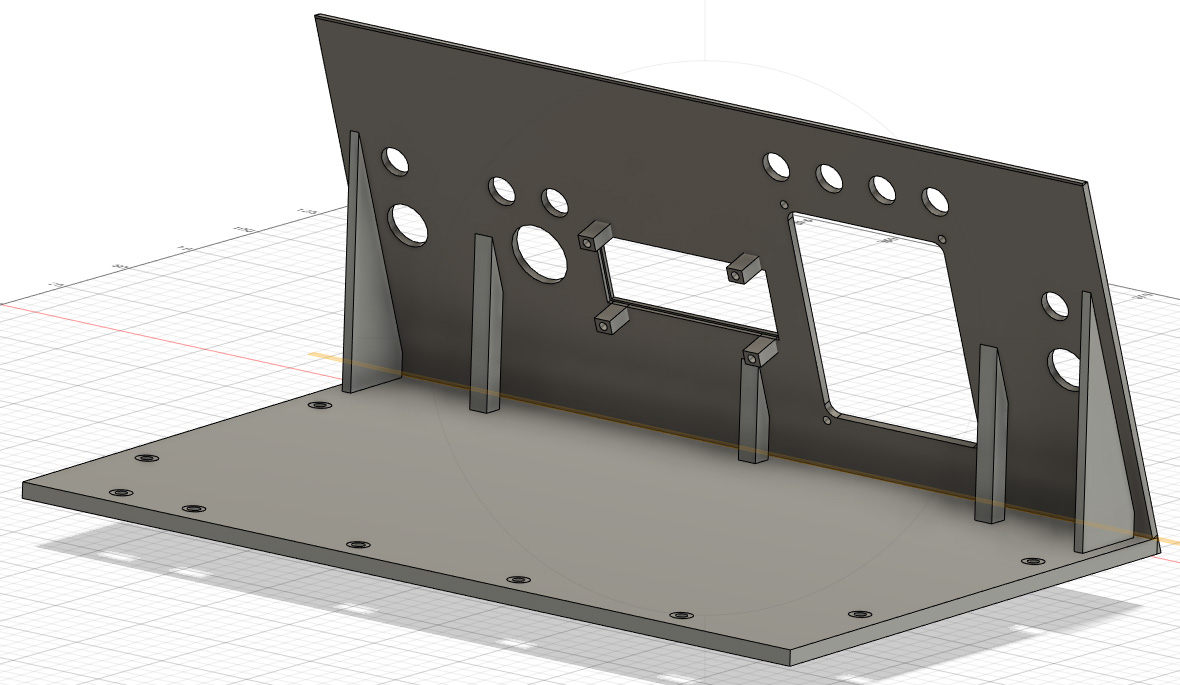
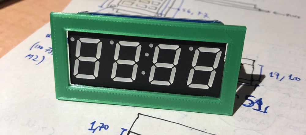
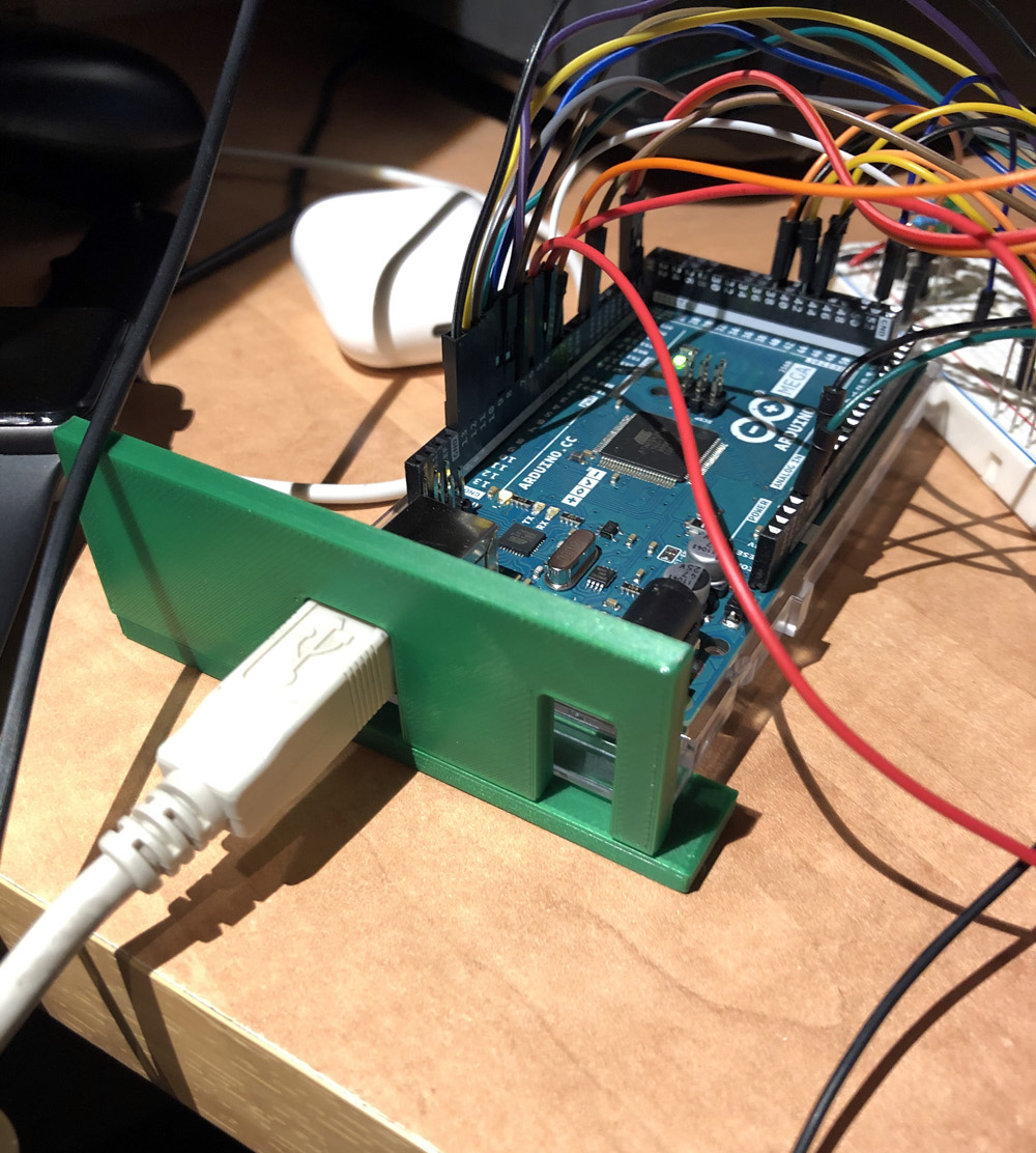
I also printed some minor parts first to make sure the spaces, holes and sizes were correct and all the elements could be attached without any problem:
|
|

|

|
|

|
As a reminder for myself, designing the box to avoid the screws on the top-side of the box maybe wasn't the best idea since now there's a small gap between the front and the other walls (everything holds together using the bottom screws and nothing else). I probably won't redesign it for now, but that's a lot of feedback I'll definitely use for the next project.
|
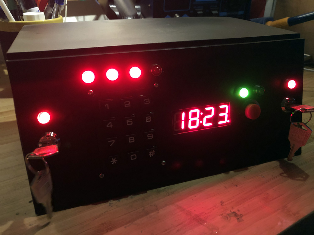
So, the clock displays the time, that's nice!
In clock mode:
Once entering the config mode the user can swap between setting the current time or the alarm time. When setting the current time there'll be two dots on the first two digits; when switching to the alarm, those dots will be in the last two digits. The config mode changes the clock to 24h mode.
I have no plans to continue with this project but here there're some annotations and thoughts about future improvements:
Special thanks to my friends Jorge and Sofia for the text review and grammar corrections.