The other day (well, at the time of writing it was the other day) I was looking at my NES Mini and started thinking about connecting it to something like an Arduino or, maybe, turn it into some game controller to use with my computer. There're lots of these solutions on the Internet, of course, but I thought about poking around with the device and try to learn something in the process.
(after finishing some things here I discovered this library that covers more devices and does more stuff. Take a look if you want to manage different types of Extension Controllers)
The NES Mini Controller (and the SNES equivalent, since they're basically the same but with more buttons, more or less) uses an I2C bus interface to connect with the console. This mechanism is also used by some "complements" that are connected to the Wiimote, extending their functionality with things like the nunchuk.
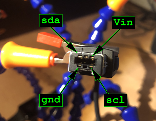
With an I2C bus on mind, we need at least 4 pins from the controller in order to be able to establish a connection: VIN, GND, SDA and SCL (3.3v on VIN, by the way). There're lots of schematics over the Internet, so the connector would look like this:
Then we wire them to the I2C pins on the Arduino (A4 for SDA and A5 for SCL on the UNO model), attach the 3.3v for VIN and the GND:
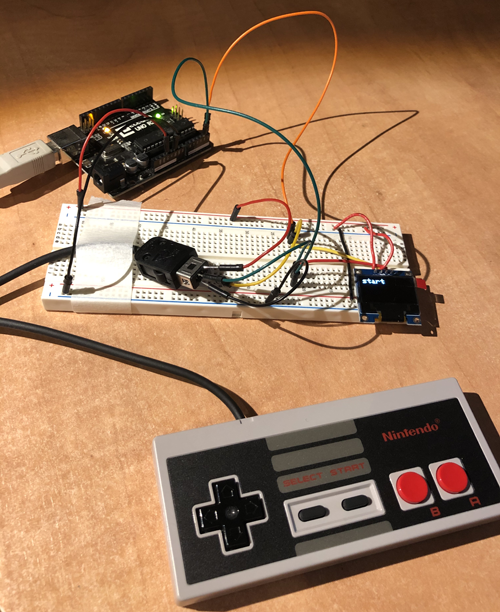
I also connected a small OLED screen via I2C too (remember: same pins, different address!) to have a fancy output device to check the controller inputs.
Speaking about addresses, those controllers use the 0x52. I didn't knew that, so I searched for it used an I2C bus address scanner to figure it out
(the Arduino itself can handle all the I2C stuff with the Wire lib):
void setup() {
	Wire.begin();
	Serial.begin(9600);
}

void loop() {

	for (int i = 0; i < 127; i++) {
		Wire.beginTransmission(i);
		int error = Wire.endTransmission();

		if (error == 0) {
			Serial.print("found on address ");
			Serial.println(i);
		}
	}

	delay(1000); // will scan forever
}
This loops for the 127 possible addresses and tries to connect to each one, outputing only the successful attemps (which, again, for this controllers will be the 0x52).
Once connected I first tried to read some bytes for the bus to see if the button pressing changes anything, but that didn't work. After some research I noticed that, in order to read the button status, first we need to "ask for the data" by writing 0x00 to the bus. Also the amout of bytes to read is 6 each time, since the last two are the ones with the buttons information.
Also, according to this Wiibrew page the SNES Mini requires to be initialized by writing 0x55 to address 0xF0 and 0x00 to 0xFB. This means an initial transmission like that:
// send 0x55 to 0xF0
Wire.beginTransmission(this->address);
Wire.write(0xF0);
Wire.write(0x55);
Wire.endTransmission();
delay(10);

// send 0x00 to 0xFB
Wire.beginTransmission(this->address);
Wire.write(0xFB);
Wire.write(0x00);
Wire.endTransmission();
delay(10);
Now we need to map each group of bytes to the buttons (allowing a multi-button detection). We're going to store the values for each single button as an array of bits. Then, in every loop it will request for the input bytes and, with those bytes:
I've written a small library for testing all of this, paired with a simple sketch to show the whole setup:
In the sample code here there's an array of "pressed buttons" in order to show them in the serial monitor. The OLED screen is only outputing the "any button pressed" vs the "no button pressed" but at this point we can proceed however we want to process those inputs (the OLED handling is done via Adafruit SSD1306 Monochrome OLED library).
I'm not a C++ expert so I'm sure there're some improvements we can do to fetch the data in a better way. For the moment, this works pretty well as a proof of concept (and I asume it can be attached to a micro with USB capabilities -like the ATmega32U4- and turn the whole system into a gamepad, for example).